
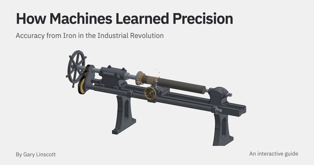
Accuracy from Iron in the Industrial Revolution This is a screw-cutting lathe of the kind Henry Maudslay built in London around 1800. A labourer turns the large wheel to spin the bar in the middle, and a cutting tool moves along beside it on a carriage that slides on straight iron rails. A long screw moves the carriage the same distance on every turn of the bar, cutting a thread into its surface.
Lathes like this made shafts and screws for steam engines, looms, locomotives and other lathes. But the lathe's own parts have to be accurate first. If a rail is bent, the tool follows the bend.
If the turns of the screw are unevenly spaced, the thread it cuts will be uneven too. These errors leave pistons leaking, shafts wobbling in their bearings and nuts jamming on their bolts. In the 1770s, workshops were still struggling to make large cylinders round, long rails straight and screw threads evenly spaced.
Even checking their work was difficult: the smallest mark on an ordinary workshop rule was a sixteenth of an inch, about a millimetre and a half. By the 1850s, Joseph Whitworth had built a machine that could detect a difference of a millionth of an inch. In this article we'll follow how workshops learned to make flat surfaces, cut accurate screws and measure their parts, using interactive figures to explore each step (try rotating the lathe above with two fingers, or pinching to zoom and dragging the lathe above, or zooming with ⌘/Ctrl + scroll).
Let's start with the cylinder of Watt's steam engine, which we built in the previous article. The cylinder Newcomen's engine filled a cylinder with steam, then condensed it with a spray of cold water. The atmosphere pushed the piston down into the partial vacuum, but the spray also chilled the cylinder.
Watt moved the condensation into a separate cold vessel so that the cylinder could stay hot, saving about two thirds of the coal. This also meant he had to change the way he sealed the piston. Below, we can compare the two engines.
Newcomen kept a pool of water on his piston to fill the gaps against the uneven cylinder wall. Water would have cooled Watt's cylinder, so he used dry packing instead. The tightly rammed packing couldn't give way enough to fill the gaps, so the hole through the cylinder, called the bore, had to be round and straight along the whole stroke.
The cylinders of the 1760s were far from that. The eighteen-inch cylinder of Watt's test engine at Kinneil, in 1769, was about ¼ of an inch wider one way than the other at its worst point. That is nearly a centimetre of error in a cylinder less than half a metre wide.
The traditional way to make two parts fit was to press them together and file away the bright spots where they rubbed. The workman doing this was called a fitter. He could make the small surfaces of a valve or a gun lock fit closely, but a piston had to fit at every point along its stroke.
Filing one part of the bore wouldn't make the rest match, and most of it was deep inside the cylinder, where a file couldn't reach. To see why this was such a challenge, let's go through how the cylinders were built. The thick iron walls were made in one piece by pouring molten iron into a mould, a process called casting.
The mould formed the outside, while a core in the middle left a hole through the iron. Below, we can watch a cylinder being cast in a sand mould. Molten iron is far denser than sand, so it pushes the core upward against whatever holds it down.
If it lifts even slightly, the casting is ruined. Even a core that stays in place leaves a rough hole that isn't straight or round. A boring mill cuts away the inside of the casting to bring it to the right shape and size.
The boring mills of the time held the cutter on the end of a long bar supported from one side, like a broomstick held at arm's length. The bar sagged under its own weight, and the uneven wall pushed it from side to side as it cut. Instead of making a straight hole, the cutter followed much of the crook...
Sumber: Hacker News · Diringkas oleh HeadlinesBriefing